Tracking the Tokamak – The Holy Grail of Renewable Energy
Project Description
A national laboratory dedicated to research of fusion as a safe and renewable energy alternative has built a tokamak as a research tool. A tokamak is a fusion machine that uses magnets to harness super hot plasma (the 4th state of matter) and fuse atoms together, in doing so, creating energy. Fusion, the process that powers the sun and stars, is the holy grail of renewable energy, and scientists are trying to replicate the process on Earth. If humans can harness the power of the stars, Earth could have virtually unlimited energy for millions of years without contributing greenhouse gases, with little risk, and available to all. This tokamak is a research instrument.
The Challenge
This laboratory would like the ability to accurately align/adjust equipment to be relative to the tokamak’s vacuum vessel. As part of its experiment, this Laboratory asked East Coast Metrology (recognized as ECM – Global Measurement Solutions) to characterize magnet geometry and establish a network of permanent control points. A global coordinate system will be used to easily describe three-dimensional spatial relationships between all geometry and control points. The coordinate system will be constructed from datum feature information provided by the laboratory. Once the coordinate system is established, being relative to the coordinate system is the same as being relative to the tokamak itself.
In order to be relative to the tokamak’s vacuum vessel, reference features with known locations need to be defined. The reference features to be used are 0.5” and 1.5” SMR control points. When at least three control points are measured, the measuring instrument can align itself to the tokamak’s coordinate system. The laboratory wanted at least 40 permanent control points on the outside of the tokamak vessel as well as 16 on the inside of the vessel. All these permanent control points need to be relative to the tokamak’s coordinate system with an uncertainty of under 0.007”. The tokamak is spherical, spans three stories and has openings to the inside from the top and bottom. Clearly, line of sight is an issue, and in some cases, there is no way to measure certain points from a single instrument location.
There are other features that ECM defined relative to the tokamak’s coordinate system. The magnets, or poloidal field coils, wrap around the tokamak both vertically and horizontally. One of the features is the centerlines of the vertical coils and horizontal coils need to be defined with an accuracy of +/- 0.015” or better.
The Solution
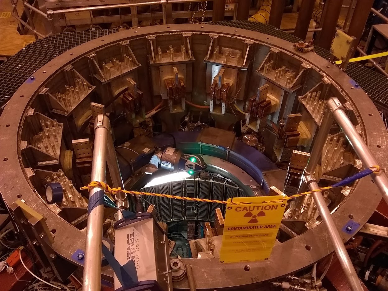
To achieve +/- 0.007” location accuracy of the permanent control points on the tokamak’s vacuum vessel, a Unified Spatial Metrology Network (USMN) needed to be created. To overcome line of sight issues caused by the size of the tokamak, and obstructed views, roughly 100 tracker positions were set up over three platform levels. The USMN feature within the Spatial Analyzer software was used to perform a weighted bundle adjustment of all the trackers, and their measured control points. The USMN feature calculates the uncertainty of each control point and creates a nominal point that has greater certainty of its location to its true value. Relation between points that have no line of sight between one another (such as points on opposite outside sides of the vessel or on different flooring levels), needs to be created through other tracker positions. This method of “leap-frogging” adds more uncertainty to the actual relation of the points. The uncertainty can be minimized by “leap-frogging” from a different path such as “leap-frogging” clockwise around the vessel if the original path was counter-clockwise. “In order to make our USMN reach the desired accuracy, we had to create multiple line of sight paths to connect points inside and outside of the vessel, on different platform levels, and on opposite sides of the vessel. Our rule of thumb was to measure every point at least three times,” explained Jon McLaughlin, ECM Certified Metrologist. Measuring every point three times helps with “leap-frogging”, but it also aids in diminishing the uncertainty of individual measured points. For every laser tracker measurement there is a degree of uncertainty caused primarily by the angular encoders.
To work as efficiently as possible while measurements were taken for the USMN, other desired features were captured. The most complex feature the laboratory needed relative to the tokamak’s coordinate system was the vertical coils and horizontal coils. This task required the use of the AT960 with the LAS scanner. This instrument allowed ECM to quickly measure these features and provided enough data to accurately model the features. Once a model was created from the scan data, ECM could easily report the centerline of the coils.
Most laboratories and manufacturers generally have adequate tools, and staff with the metrology experience to use them; however, for many applications best-in-class equipment and world-class metrologists are required. Ultimately, equipment is only as good as the technicians who operate it, and it’s in this sense that metrology service companies are instrumental in the process. ECM technicians are certified to the Coordinate Metrology Society’s Level-1 and Level-2 Certifications, which means that their skills are validated by the industry’s most complete and practical body of knowledge. By utilizing ECM, this national laboratory was able to accomplish the required scan job of the tokamak in record time with the most efficient combination of technology, providing the most accurate results.
The Importance of Choosing the Proper Equipment
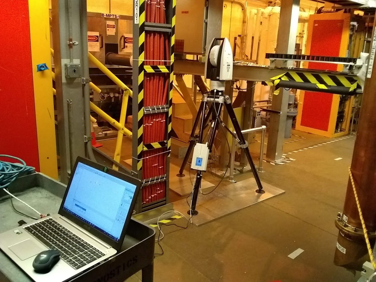
This unique application called for multiple metrology instruments working together to create one solution. Due to the size of the tokamak and the accuracy required, laser trackers were the preferred instrument. ECM’s unique position in the industry allows it to partner with several leading Original Equipment Manufacturers (OEMs) in order to provide our customers with the most accurate and efficient metrology solutions. For this particular application, four separate laser trackers where used, each providing unique functionalities. The Leica AT401 and AT402 provide the ability to easily move from one location to the next, due to them being lightweight and possessing battery back-up capabilities. The AT401 and AT402 also possess the ability to shoot directly up, which became useful at the bottom opening to the tokamak. The Faro Vantage tracker can measure objects in confined spaces, as well as mount horizontally to see into the tokamak from the top opening. The AT960 has the same capabilities as the Faro Vantage, in addition to some special accessories the other trackers don’t. One of these special accessories is the Leica Absolute Scanner (LAS). The LAS can capture mass amounts of data (point clouds) through non-contact measuring.
