Originally published in Quality Magazine, © [2026] BNP Media.
Written by Gary C. Confalone, East Coast Metrology.

East Coast Metrology (ECM), part of the Measurement & Alignment Services Division of In-Place Machining Company (IPM), is pleased to share that Quality Magazine recently published an article authored by Gary Confalone, Vice President of ECM, titled “Understanding Dimensional Metrology: Choosing the Right Tool for the Job.”
In this article, Gary explores how manufacturers can navigate an increasingly complex landscape of dimensional measurement technologies—selecting the right tools to ensure accuracy, efficiency, and confidence in critical inspection and validation processes.
Getting Familiar with CMMs, Laser Trackers, Portable Arms, and Laser Scanners
Every manufactured product, from a smartphone component to a commercial aircraft, relies on precise dimensional accuracy. Even small deviations from the intended design can lead to assembly problems, performance issues, or product failure.
Dimensional metrology is the science of measuring the size, shape, and position of objects to ensure they meet engineering specifications. In manufacturing, this discipline provides data that verifies whether parts conform to their digital designs and tolerance requirements.
Today’s manufacturers rely on a wide range of advanced measurement tools to perform these inspections.
Some are stationary systems designed for ultra-high precision in controlled laboratory environments. Others are portable instruments capable of measuring large assemblies directly on the shop floor.
As manufacturing systems become larger and more complex, selecting the appropriate dimensional measurement technology has become an increasingly important decision for engineers and quality professionals.
Four measurement technologies are commonly used across manufacturing environments:
- Coordinate Measuring Machines (CMMs)
- Laser Trackers
- Portable Measuring Arms
- Laser Scanners
Understanding how these systems work and when to use them helps engineers and quality professionals choose the right tool for the job.

Coordinate Measuring Machines (CMMs)
Coordinate Measuring Machines (CMMs) enable manufacturers to inspect complex parts with a high degree of accuracy and repeatability. These systems are widely used in precision manufacturing environments where dimensional verification is critical to product performance and regulatory compliance. Their ability to perform automated inspection routines makes them particularly valuable when verifying large volumes of components built to the same design.
A CMM measures parts by recording the precise coordinates of points on a component surface within a three-dimensional coordinate system defined by the X, Y, and Z axes. A probe attached to the machine physically touches points on the part, allowing the system to record their exact positions in space. By collecting multiple measurement points, the software can calculate geometric features such as holes, slots, planes, cylinders, and complex surfaces.
Once the measurement data is collected, inspection software compares the measured geometry to the original CAD model or engineering drawings. This allows manufacturers to verify dimensional tolerances, confirm geometric relationships, and ensure that the part meets design specifications.
A typical CMM structure includes:
- A rigid granite base that provides dimensional stability
- Precision linear guideways that ensure smooth and accurate motion
- Three orthogonal motion axes (X, Y, and Z)
- A touch probe or scanning sensor
- Measurement and inspection software
In many modern systems, the probe can automatically index to different orientations, allowing the machine to access features located at multiple angles. In addition to traditional touch probes, CMMs may also be equipped with scanning probes or sensors, which allow the system to gather larger sets of surface data while maintaining high accuracy.
Because thermal expansion can influence precision measurements, CMMs are typically installed in temperature-controlled quality laboratories where environmental conditions remain stable. Maintaining a consistent temperature minimizes dimensional changes in both the machine and the parts being measured, ensuring reliable measurement results.
CMMs are widely used throughout manufacturing for first article inspection, process validation, and final quality verification. Engineers often rely on CMM data to confirm that new tooling or machining programs are producing parts within specification before full-scale production begins.
CMM systems are commonly used to inspect:
- Aerospace structural components and turbine parts
- Automotive engine, transmission, and drivetrain components
- Medical implants and surgical instruments
- Precision machined components
- Injection molded plastic parts
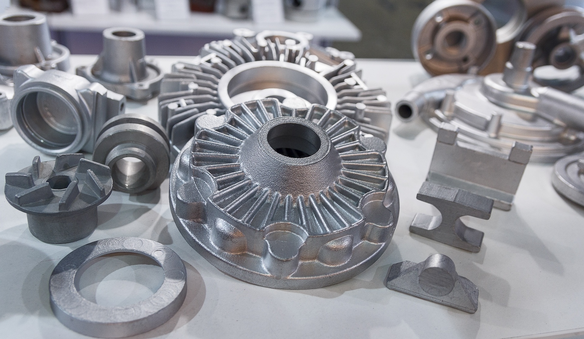
- Cast and forged components
In aerospace and medical industries, CMM inspection plays a critical role in traceable quality documentation, where measurement results must be recorded and maintained to meet strict regulatory standards.
CMMs are also commonly used for geometric dimensioning and tolerancing (GD&T) verification, allowing manufacturers to confirm that complex geometric relationships, such as position, concentricity, flatness, and profile, meet design requirements.
Because CMMs can execute automated inspection programs, they are well suited for repetitive inspection tasks. Once a measurement routine is created, the system can inspect multiple identical parts with minimal operator intervention, ensuring consistent measurement procedures and reducing the potential for human error.
CMMs are typically selected when:
- Parts are small to medium in size
- Extremely tight tolerances must be verified
- Inspection occurs in a controlled laboratory environment
- Multiple parts of the same design require consistent inspection
In many manufacturing operations, CMMs serve as the primary reference for dimensional verification, providing the high accuracy and repeatability required for validating critical components and maintaining overall product quality.
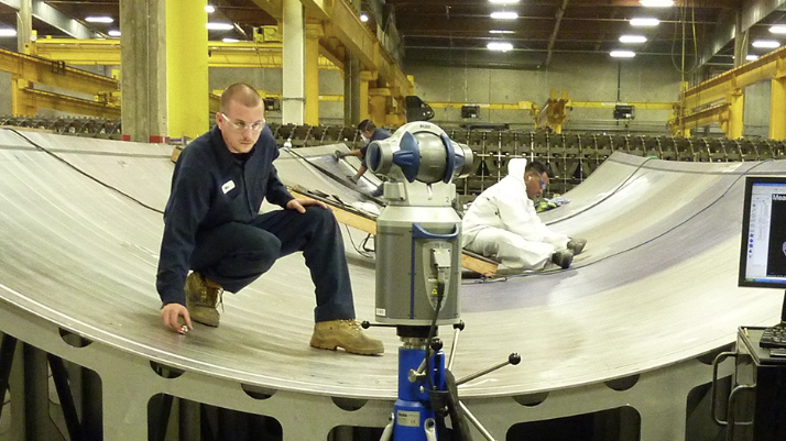
Laser Trackers
As manufactured components and assemblies continue to grow in scale, the limitations of stationary metrology systems become increasingly apparent. Traditional coordinate measuring machines (CMMs) are typically confined to laboratory environments and limited measurement volumes. When dealing with large structures or assemblies that span several meters, or even tens of meters, portable metrology solutions become essential.
Laser trackers address this need by providing highly accurate, portable coordinate measurement capability for large-scale measurement and alignment applications. These instruments are designed to measure the three-dimensional position of targets across large volumes, often covering measurement ranges of 30 meters or more from a single setup. Their portability allows measurements to be performed directly on the shop floor, in assembly bays, or in field environments where large components cannot easily be moved.
Rather than contacting the part directly with a probe, a laser tracker measures the position of a reflective target known as a spherically mounted retroreflector (SMR). The SMR contains precision optics that return the incoming laser beam directly back to the tracker regardless of its orientation, allowing the system to determine the exact spatial location of the target.
The position of the SMR is calculated using three fundamental measurements:
- Distance to the reflector
- Horizontal angle (azimuth)
- Vertical angle (elevation)
By combining these values, the system calculates precise 3D coordinates of the target relative to the tracker’s position. Modern systems can achieve measurement accuracy within tens of microns across large volumes.
Beyond simple measurement, laser trackers are widely used as precision alignment tools during the assembly and installation of large mechanical systems. Because they provide real-time positional feedback, technicians and engineers can monitor component movement and alignment as adjustments are made. This capability allows large structures to be positioned within tight tolerances that would be difficult or impossible to achieve using conventional mechanical methods.
Laser trackers are commonly used in industries where assemblies are extremely large or require precise alignment across long distances, including:
- Aerospace manufacturing
- Aircraft fuselage and wing alignment
- Shipbuilding and modular ship section assembly
- Tool building and large mold alignment
- Automotive production
- Robot calibration and kinematic verification
- Fixture and tooling alignment
- Assembly line layout and installation
- Power generation equipment installation
- Wind turbine blade profile inspection
In alignment-focused applications, laser trackers play a critical role in tasks such as:
- Aligning aircraft fuselage sections during assembly
- Positioning large machining centers and gantry systems
- Aligning turbines, generators, and rotating machinery
- Verifying the position of robotic cells and automated equipment
- Roller, shaft, and rail system alignment
- Aligning rail systems, conveyor lines, and manufacturing transfer systems
- System bore-sighting and harmonization
Because measurements can be taken over long distances without repositioning the instrument, laser trackers significantly reduce setup time when compared with conventional metrology tools. In addition, their ability to provide continuous feedback allows operators to monitor alignment adjustments in real time, improving both accuracy and efficiency during installation or assembly processes.
Laser trackers are often selected when:
- Parts or assemblies are several meters or larger
- Measurement must be performed directly on the shop floor or in the field
- Components cannot be transported to a controlled laboratory environment
- Real-time positional feedback is required for alignment or adjustment
In these environments, laser trackers serve not only as measurement devices but also as critical tools for large-scale precision assembly, enabling manufacturers to achieve tight tolerances even when working with structures that span entire buildings.

Portable Measuring Arms
Portable measuring arms, often referred to as articulated arms or portable coordinate measuring machines (PCMMs), also provide a flexible alternative to traditional stationary metrology systems. These devices combine the coordinate measurement capability of a CMM with the mobility required for shop floor environments, making them particularly useful for inspecting parts that are difficult to bring into a dedicated metrology lab.
A portable arm consists of multiple articulated joints connected by rigid arm segments. Each joint contains high-resolution rotary encoders that continuously track the angular position of the arm. As the operator moves the arm through space, the system calculates the exact position of the probe tip relative to the arm base.
When the probe touches the surface of a part, the software uses the encoder data to determine the precise three-dimensional coordinates of the measurement point. By collecting a series of points across a component, the system can evaluate geometric features such as holes, slots, edges, planes, and complex contours.
Portable arms can be equipped with a variety of measurement sensors depending on the application. In addition to traditional contact probes, many systems support laser scanning attachments that allow users to rapidly capture thousands of surface points per second. This capability makes articulated arms useful not only for dimensional inspection but also for surface digitization and 3D modeling tasks.
Advantages of portable measuring arms include:
- Easy setup and mobility
- Quick measurement of medium-sized parts
- Direct inspection on the production floor
- Real-time feedback for assembly and alignment adjustments
- Lower cost compared to large bridge CMM systems and Laser Trackers
Because of their portability, real-time feedback, and ease of use, articulated arms are widely used throughout manufacturing operations for both inspection and engineering tasks.
Portable arms are frequently used for:
- Tooling and fixture inspection
- Mold and die measurement
- Reverse engineering of legacy components
- Shop floor quality checks
- First article inspection (FAI)
- Verification of machined parts and fabricated weldments
- Inspection of composite and plastic components
- Digitizing parts for CAD model generation
- Rapid comparison of manufactured parts to CAD data
In production environments, portable arms are often used to perform in-process inspection, allowing operators to verify part dimensions immediately after machining or fabrication. This reduces the need to move parts to a centralized inspection department and enables faster feedback when process adjustments are required.
They are also commonly used during tooling development and fixture setup, where engineers must verify the location of locating pins, clamps, blocks, and reference surfaces. The ability to quickly measure features and compare them to CAD data in real-time allows adjustments to be made before production begins.
Portable arms are most effective when:
- Parts are medium sized and within the arm’s measurement volume (~ 3 meters)
- Measurements must occur directly on the shop floor
- Flexibility and speed are important factors
- Components must be inspected in multiple locations within a facility
- Real-time feedback is required during assembly
For many manufacturers, portable measuring arms serve as a practical bridge between laboratory metrology and production operations, providing accurate dimensional verification while maintaining the speed and accessibility required in modern manufacturing environments.

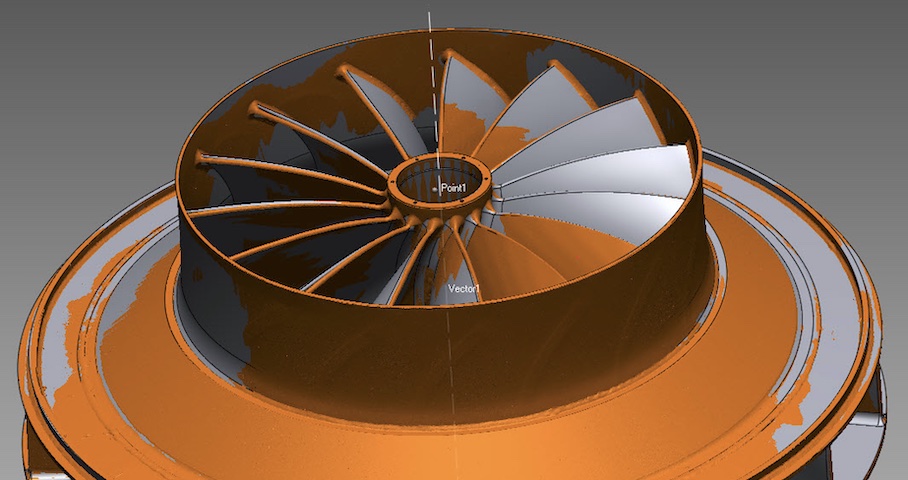
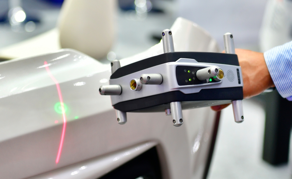
Laser Scanners
While traditional metrology systems measure individual points on a part, laser scanners are designed to capture entire surfaces quickly and densely, generating large sets of three-dimensional data. This capability allows engineers and quality professionals to evaluate complex geometries that would be difficult or time-consuming to measure using discrete point methods.
Laser scanners operate by projecting a laser line or structured light pattern onto the surface of a component while one or more cameras observe the reflected light. As the scanner moves across the part, the system continuously captures the deformation of the projected laser line. Using triangulation principles, the software calculates the precise three-dimensional position of thousands of points along the surface.
The result is a dense point cloud representing the full geometry of the scanned object. This point cloud can then be converted into a polygon mesh or compared directly to a CAD model to evaluate dimensional accuracy and surface variation.
In many modern metrology workflows, laser scanners are not standalone systems but are instead used as detection probes integrated with other measurement platforms.
Various types of laser scanning sensors can be mounted on:
- Coordinate Measuring Machines (CMMs)
- Laser trackers
- Portable articulated measuring arms
When used on a CMM, a laser scanner allows the machine to capture dense surface data in addition to traditional touch-probe measurements. On portable arms, scanning probes enable operators to quickly digitize complex parts directly on the shop floor. When paired with a laser tracker, scanning sensors can measure varying surfaces and assemblies across extended volumes while maintaining the long-range accuracy of the tracker system.
Modern laser scanners can capture a large amount of point data in a short span of time, enabling rapid inspection of complex surfaces and freeform geometries. Because of this speed and data density, laser scanning has become a key technology in industries where detailed surface analysis and digital inspection workflows are required.
Laser scanning is widely used for:
- Surface deviation analysis
- Reverse engineering of physical parts into CAD models
- Inspection of contoured or freeform components
- Tool and mold verification
- Additive manufacturing validation
In manufacturing environments, laser scanners are frequently used to perform full-surface comparisons between a manufactured part and its original CAD design. Inspection software generates color deviation maps that visually highlight areas where the part deviates from nominal geometry. This analysis helps identify distortion, machining errors, material shrinkage, or tooling wear.
Laser scanners are also widely used in industries that produce complex aerodynamic or sculpted components, such as aerospace, automotive, and energy production. Manufacturers may scan turbine blades, automotive body panels, composite structures, or cast components to verify that the final shape conforms to design specifications.
In tooling and mold manufacturing, scanning enables engineers to verify the geometry of molds, dies, and forming tools. Over time, these tools may experience wear or deformation due to repeated production cycles. Periodic scanning allows manufacturers to detect dimensional changes early and perform maintenance before product quality is affected.
Laser scanners are also commonly used in reverse engineering applications, where a digital model must be created from an existing physical object. This is particularly valuable when original CAD data is unavailable, such as with legacy components, replacement parts, or older equipment. The scanned data can be processed into a digital model that engineers can modify, analyze, or reproduce.
In additive manufacturing workflows, scanning is often used to validate printed components by comparing the finished part to the original design model. This helps identify build distortion, dimensional inaccuracies, or surface irregularities that may occur during the printing process.
Laser scanners are most appropriate when:
- Parts have complex shapes or freeform surfaces
- Dense surface data is required for analysis
- Inspection speed is important
- CAD comparison or reverse engineering is required
- Full surface visualization is needed rather than discrete point measurement
- Choosing the Right Metrology Tool
Each dimensional metrology system serves a different role in manufacturing.
Table 1: Comparison of Dimensional Metrology Technologies
| Instrument | Best For | Typical Size Range | Strength |
|---|---|---|---|
| CMM | Precision part inspection | Small–medium | Highest accuracy |
| Laser Tracker | Large assemblies | Large structures | Long measurement range |
| Portable Arm | Shop-floor inspection | Small–medium | Flexibility |
| Laser Scanner | Complex surfaces | Any size | High-speed data capture |
Conclusion
Dimensional metrology plays a critical role in ensuring that manufactured parts meet their intended design and performance requirements. Without accurate measurement, it would be impossible to maintain quality, consistency, and safety in modern manufacturing.
From micron-level inspection of precision components to measuring aircraft assemblies spanning dozens of meters, today’s metrology tools provide manufacturers with the data they need to build reliable products.
Today’s modern metrology instruments are no longer just for inspection; they’ve become an integral part of the production process, ensuring quality at every stage of manufacturing.
“Today’s modern metrology instruments are no longer just for inspection; they’ve become an integral part of the production process, ensuring quality at every stage of manufacturing,”
Gary Confalone, Vice President, East Coast Metrology
While countless instruments exist for different dimensional measurement applications, understanding the capabilities of CMMs, laser trackers, portable arms, and laser scanners is the first step toward selecting the right solution and ensuring every part leaving the factory meets the standards it was designed to achieve.
At East Coast Metrology, we see these challenges play out every day across industries where accuracy and repeatability are critical. From portable metrology and laser tracker measurement to ISO/IEC 17025-accredited calibration, our team applies the same principles outlined in this article to help customers validate quality and maintain confidence in their processes.
For more information on the services provided by the Measurement & Alignment Services Division of In-Place Machining Company, please contact us today.