Course Description:
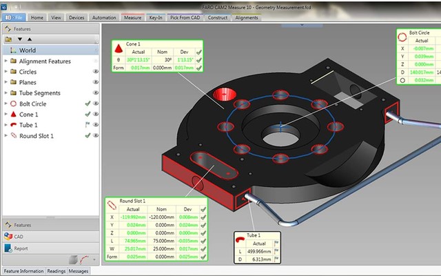
FARO’s CAM2 inspection software packages for the FARO Arm. They are engineered for computer-aided measurement supporting 3D feature measurement/inspection and CAD-to-part comparison.
More About This Course
The instructor will work with students to define or influence a metrology process providing controlled dimensional quality in engineering and manufacturing of an application specific to the students’ work environment carried out by using the laser tracker. Students will apply learned topics in the course to practical situations so they gain an appreciation of the nature of the work. The students will work towards defining a systematic approach to establishing the correct methodology and providing a measurement based process for managing an inspection job correctly.
This is done by associating the students’ knowledge of the fundamentals of measurement with the measurement science concepts:
Dimensional Metrology
Introduce measurement uncertainties relative to dimensional metrology, sources of error, and the effect of the measurement environment
Define the difference between measurement accuracy and measurement error and tolerance limits
Introduce maintaining measurement traceability
Physical Metrology
Application of measurement principles as applied to physical properties; for example, measurement of temperature (ambient and object) and monitoring scale change of the part being inspected
Identification of sources of error and applying techniques to minimize error
Quality Control and Inspection
Application of methodologies for analysis of the results in the inspection process
Solution of quality problems to the inspection process
Reporting methodology to ensure positive and unambiguous transfer of technical information
Selected examples of applications: tooling building & certification, part inspection, first article inspection, alignment, and surface profiling.
Course Outline
Measurement Exercises
- Select Probes
- Part Measurement – covering basic inspection of simple geometries and examining their relationships (theoretical versus actual measurement)
Measurement Accuracy – Applying Good Measuring Principles
- Effects of temperature
- Targets and target offset
- Environmental effects
- Physical changes in the part or stand
- Measurement strategy
Reporting
- Simple format
- Tabular format
- Quick reporting
Scanning
- Inspecting surfaces
- Freehand scanning
- Parallel lock planes scan
- Editing scan data
Dimensions
- Describing the relationship between two or more features
- Construct angles, lengths and whiskers
Part Inspection with CAD
- CAD Data file formats
- Translating and adding the CAD data
- CAD to part alignments
- CAD=Part
- Iterative alignment (best-fit)
- Scaling
Moving the FARO Arm (Device) Position
- Moving the FARO Arm
- Realigning the FARO Arm with respect to the part
- Check the quality of the move
DRO Window
- Dynamic DRO Window
Nominal
- Nominal is the design value of a feature
- Adding nominal values
- Entering values
- Importing from CAD
- Constructing nominal values
Coordinate Frame Systems
- Common coordinate frame systems
- Constructing the alignment
- Feature reducibility
- Rotation of a coordinate system
- Translation of a coordinate system
Feature Measurement
- Types of Features
- 2D Features
- 3D Features
- Measuring geometric features
- Compensating for measured features
- Plane compensation
- compensation of a 2D feature
- Checking the Validity of the Data Collected
- Geometric Constructions
Probe Calibration and FARO Arm Certification
- Calibration and certification
- What is calibration?
- FARO Arm
- Probes
- What is certification?
- Is the FARO Arm performing within specification?
- Single Point Method
- Probe calibration
- XYZ location
- Probe calibration error
- Single Hole Method
- Sphere Method
Introduction to CAM2 Measure
- Starting CAM2 Measure
- Screen layout
- Graphics field
- DRO Window
- Pull-down menus
- Toolbar buttons
- Prompt Bar
- Status Bar
- Hotkeys
- Measurement Device (FARO Arm) Setup – establish communication
Hardware Overview – FARO Arm
- FARO Arm Control Station
- Setting up the FARO Arm
- Connecting to the computer
- Referencing the encoders
- FARO Arm Handle Buttons
Software Installation
- CAM2 Measure
- Hardware lock driver
- Support documentation
Introduction to Coordinate Geometry
- What is a coordinate frame system?
- 2D geometry
- 3D geometry
- Right Hand Rule
- Translating a coordinate frame system
- Rotating a coordinate frame system
- Establishing control points – using them as a reference to check drift and move the measuring device
- Measuring the part
- Establishing an alignment
- Translating and adding the CAD data
- Setting an iterative alignment
- Constructing geometries
- Switching between Coordinate Frame Systems
- Moving FARO Arm position
- Printing and saving a report
Care of the FARO Arm
- Transportation
- Storage

