Revolutionizing Aircraft Assembly Using Metrology-Based Automation
Project Description
A world-famous manufacturer of commercial and business aircraft was seeking an automated solution to assemble major components of their new state of the art aircraft. The project goal was to streamline the assembly process using metrology based automation that could feed transformation calculations to the PLC of the automated position system allowing an operator to move the aircraft component into the optimal join position. The manufacturer found the desired solution in a design offered by a design/build team comprised of Electroimpact (EI) and ECM – Global Measurement Solutions (ECM).
The Problem
Historically, the manufacturer used static tooling jacks and manual linear movements to handle the moving of aircraft parts on the assembly line. This process resulted in complications joining the aircraft components based on manufacturing variations in the parts and the skill level of the personnel on the shop floor. To help eliminate these variables, they were seeking a solution that offered greater accuracy, faster assembly times and a real-time feedback loop to the automated join tooling and the shop floor personnel performing the join. Other locations had been using a combination of lower accuracy iGPS technology for measurement feedback and a tooling scheme that was not integrated into a computer for monitoring and commanding the tooling jacks and positioners. Ultimately, the team wanted a highly accurate and tightly integrated solution utilizing a graphical interface to minimize aircraft joining complexity, thus helping to reduce the need for specially skilled personnel.
The manufacturer selected the team comprised of Electroimpact (EI), designers and fabricators of sophisticated tooling solutions in the aerospace sector, and ECM-Global Measurement Solutions (ECM), recognized for their application of high accuracy metrology in a wide variety of measurement and alignment challenges. The manufacturer considered each company’s experience and track record of tooling and metrology, focusing on quality of design. They wanted the design to be at the forefront of automated join technology using the most innovative 3D measurement capabilities, leading to the most efficient method available for automated aircraft assembly.
Based on their experience working together on various metrology automation projects, EI and ECM were well equipped to provide the manufacturer with a single, highly functional user interface placing equal emphasis on the motion control of the aircraft components and the input of the dynamic measurements providing “position awareness” of the aircraft components within the tooling join environment. The EI/ECM design build team provided the customer with a series of work cells optimizing both the alignment and assembly of the aircraft with a reliable, easy to operate and efficient solution.
The Importance of Choosing the Proper Equipment
The manufacturer wished to include EI and ECM in the very beginning of the design phase, ensuring their metrology and tooling expertise were part of the work cell concepts they were considering. ECM investigated several potential metrology technologies during the design review process and ultimately found laser trackers would provide the best combination of accuracy, flexibility, automation potential, at a reasonable cost. Systematically evaluating the available laser trackers and demonstrating specific models to the FAL Team resulted in the final selection of Hexagon Metrology’s Leica AT401/402 laser tracker. The AT401/402 was relatively new to the market, but had already demonstrated its value on other programs within the aerospace community as an excellent instrument for this type of automation project.
The Solution
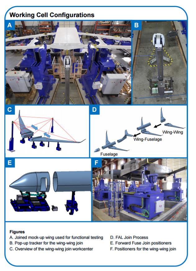
ECM engineers worked closely with EI design engineers to select optimal locations within the three major work cells for the assembly processes of the aircraft. The challenges selecting instrument locations included avoiding obstructions to the critical visibility to key features on the aircraft assemblies created by the tooling and support structure, maintaining a clear line-of-sight to control network points anchored in the concrete floor, minimizing the overall number of trackers needed to actively measure the key features of the join, and providing a secure location for each instrument to avoid exposure to potential damage from the assembly process. After a series of design reviews with the Final Assembly Line (FAL) team, the preliminary design work was approved and ECM and EI were ready to move forward with the fabrication of instrument mounts, target adapters, and to prepare for the initial “mock up” measurement and alignment testing to be performed at EI. With the instrument positions known, custom laser tracker targets were designed and fabricated to be installed at known features on the aircraft wing and fuselage components. These aircraft components were then measured at these known features until their position corresponded to nominal join locations. EI designed a telescoping laser tracker stands to be used in production gaining the optimum positioning of the instruments during use, and allowing them to retract for protection when not in use.
To ensure proper specifications were met and any costly mistakes were avoided, EI fabricated temporary work cells for each of the three join stations (wing join, wing to center fuselage join, forward and aft fuselage joins to center fuselage/wing assembly) at their facility in Mukilteo, Washington. This consisted of a partial mock-up of the aircraft in a nearby warehouse allowing for a replica of the aircraft to be measured, positioned, and placed according to the approved design. ECM and EI joined the model components of the aircraft in a dry-run format, establishing proof of concept.

Photo courtesy of Electroimpact
The Outcome
By working with EI and the aircraft manufacturer, ECM was able to verify the laser tracker target adapters, designed to replicate the aircraft components’ join position, would fit the features on each aircraft component and accurately reproduce the components’ alignment at the aircraft manufacturing facility.
For example, ECM accomplished this complex task by coordinating meetings and facilitating many discussions with metrology engineers at the wing supplier’s location and attending a live mocked up wing assembly, then performing a “dry run” join using the wing model with the actual wing join assembly tooling to ensure the work cell was ready when the supplier’s fabricated wings finally arrived on site. These efforts not only provided the manufacturer with a high level of confidence, but also resulted in some minor fine tuning to the sequencing of the wing join measurement process prior to the joining of the first production wing. “The ECM team has consistently shown integrity with respect to the mission and a close attention to detail, both so essential for metrology work. They have also stepped up to the plate and performed in the clutch. On top of that, they have proven to be very collegial partners. They are a pleasure to work with and that has made our many challenges much easier,” states Rob Flynn – Project Engineer with Electroimpact.
EI and ECM successfully collaborated together to enable the most appropriate metrology solution to be installed into the new final assembly line. In the design of the assembly line there were three major stages to be completed that involved embedding the automated measurements into the aircraft alignment and assembly. Stage one involved the wing join and required two laser trackers, several specialized laser tracker target adapters and a control network on the factory floor tying all the measurements and movements into one aircraft coordinate system. The second stage, the wing-to-center fuselage join, was more complicated and required three laser trackers integrated together to gather the necessary data facilitating the joining of the two components. Again, several specialized target adapters were required to be designed and fabricated to optimize the visibility to the key aircraft components’ features. Finally, in stage three, the forward and aft fuselages join to the center fuse/wing assembly required three laser trackers, one of which was mounted inside the aircraft for optimal visibility. A specialized target adapter, using three laser tracker targets, was designed allowing both the instruments on the outside of the aircraft and one inside to work in a common coordinate system ensuring the highest order accuracy and efficiency. All work cells have a common control network and a rail system with a moving platform allowing the large aircraft sub-assemblies, once joined, to move seamlessly to the next work cell without the need for an overhead crane or tow dolly.
Fast forward to today, and the control network has been installed, the installation and alignment of all jacks, positioners and rails are completed, and the test runs have been performed. The built flight test vehicles are in flight testing and the aircraft flight test program is progressing as planned. In addition, the first several customers’ aircrafts are in production as the final assembly line activities gain momentum. By not building this aircraft using conventional methodologies, the final assembly line provides a reduced need for specially skilled personnel typically assigned to join completed sub-assemblies.
ECM’s metrology engineers, combined with Electroimpact’s automated positioning system, have enabled the manufacturer to transition their automated aircraft assembly procedure to the next level and streamline the process, thus optimizing time and resources. The result was higher accuracy and efficiency throughout the entire assembly process, resulting in a new, very efficient aircraft assembly that has met customer expectations.


