Authored by: Ray Ryan, Retired VP – ECM – Global Measurement Solutions
Project Background
NIST Center for Neutron Research is in the process of expanding the number of beamlines for research purposes from 7 to 11 beams. The metrology tasks required to perform the installation of the new beamlines include the design and installation of a high accuracy control network throughout the area impacted by the new beamlines, the measurement and fiducialization of a 145 new glass guide segments, the alignment of each glass guide segment in its vacuum vessel and the positioning of the all the vacuum vessels within three distinct areas of the facility. The challenges for this project for NIST engineers required careful planning to achieve the required accuracy with the restrictive schedule and overcoming severe visibility restrictions within the building. This paper addresses the challenges and the methods used by the metrology team to overcome them. Their efforts provided a highly efficient method of performing the alignment and allowed non-metrologists to perform the measurement and alignment tasks with minimal assistance.
Definitions of Terms & Acronyms
NIST – National Institute of Standards and Testing
NCNR – NIST Center for Neutron Research, Gaithersburg, MD
Fiducials/Fiducialize – reference points valued relative to key feature or datum
Control Network – series of points measured to a high degree of accuracy and used to position key components within the project reference system
USMN – Unified Spatial Metrology Network
Bundle Adjustment – mathematical calculation to combine multiple measurements based on equipment accuracy, redundancy of measurements and measurement geometry.
3D Transformation/Best Fit – mathematical calculation to align two sets of data
1.0 Introduction/Overview
NIST’s Center for Neutron Research is expanding their facility to accommodate greater demand for research time using their cold-source neutron beams. ECM Global
Measurement Solutions (ECM), under contract with the NIST Center for Neutron Research (NCNR), is assisting the NCNR Alignment Team with the task of designing,
installing and aligning four new beam lines being added to their facility on the NIST campus in Gaithersburg, Maryland. The existing NCNR facility has 7 neutron beam lines. The beam line expansion entails increasing the total number to 11 beam lines. The new beam lines required NCNR to construct an additional beam hall adjacent to the existing beam hall and to create penetrations through a 5 foot thick concrete containment wall surrounding the neutron reactor.
The image below provides a general overview of the facility, including the reactor in C Hall, the beam lines passing from C Hall into the new guide hall (G Hall).
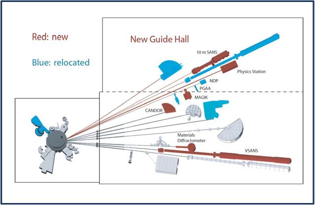
Figure 1: NIST Center for Neutron Research Beam Layout (New & Existing)
2.0 Challenges of Beam Line Expansion
The NCNR alignment team was faced with several daunting challenges in planning and executing the expansion of the beam lines. There was limited access to containment areas, pressing schedule constraints, the highest order accuracy requirements and restricted visibility along the course of the beam line. To address these challenges, the following methods were employed and are discussed in detail within the body of the paper:
Establishing facility wide control network,
Characterizing glass beam segments
Aligning C & D Hall components in temporary location,
Positioning vacuum jacket assemblies into final locations,
Using non-metrology personnel to perform all alignment tasks.
2.1 Establishing Facility Wide Control Network
To accurately align 4 beam lines spanning hundreds of feet to an accuracy of 0.002 inches requires a highly accurate control network of points valued in the project coordinate system. No measurement instrument exists that can value these points to the level of accuracy required, so a combination of instruments is used and overlapping measurements are taken from multiple locations to achieve the necessary accuracy. The measurements are “bundled” together in a highly sophisticated software package to generate statistically valid measurements with computed measurement uncertainties for each point in the control network based on the number and location of instruments used to measure each point.
The software used for this effort is New River Kinematics (NRK) Spatial Analyzer (SA) software. There Unified Spatial Metrology Network (USMN) routine within SA allows measurements from several different instruments taken from multiple locations to be combined into a singular network with accompanying accuracy statistics on how well each point is spatially defined in the network. The software serves two distinct purposes in the valuing of the control network: to compute the x, y, z values and the uncertainties associated with these values and as a design tool. SA has a simulation function that affords planners to determine the number and location of measurement devices before going into the field that will be required to achieve the level of network accuracy desired.
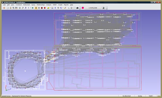
For the NCNR project, the control network starts in the reactor room (C Hall), transits through a utility room (D Hall) and enters the new guide hall (G Hall). A screen shot of the network during the design phase in SA is shown in Figure 2 on the following page. The CAD representation shows control point locations, measurement instrument positions, lines of sight (LOS) between the points and instruments and various features within the rooms for general orientation. The overall size of the three halls is approximately 200 ft by 600 ft and requires passing the control network through a small opening in the wall common to the C-D Halls. This area is the weakest point from an accuracy standpoint since the entire network “hinges” about his narrow aperture.

Figure 2 – NRK Spatial Analyzer (SA) software screen shot of control network
For the control network measurements, three types of measurement devices were necessary to achieve the project accuracy requirements: a laser tracker, a total station and a digital level. Figure 3 below provides images of the three instruments. The laser tracker provides a majority of the measurements but lacks the range to correlate points that are further than 100 feet from the instrument. This is where the total station provides the capacity to measure distances up to the entire length of the project from one instrument position. The remaining instrument, the digital level, helps enforce a level plane between points across the entire project. This is not always possible due to limited visibility between the 3 halls and cannot be guaranteed by the use of only the laser tracker and/or a total station alone.
Figure 3 – Measure devices: (A) laser tracker, (B) total station, (C) digital level
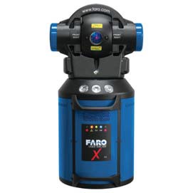
Tracker A
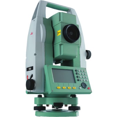
Tracker B
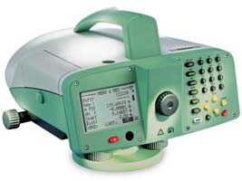
Tracker C
To accomplish the accuracy required for positioning the beam line components throughout the facility required the use of 88 laser tracker positions, 12 total station positions and 4 level loops. The specific position and orientation of the instrument positions was determined using the simulation mode in the SA software. Figure 4 below depicts the instrument positions and the lines represent the individual lines-of-sight (LOS) between each instrument and the points measured. It becomes clear that the number of observations throughout the facility is considerable to achieve the desired accuracy.
Figure 4 – SA software simulation of proposed instrument locations
The resulting accuracy calculations provide a 2 sigma (95% confidence interval) statistical indication of the point uncertainties using the proposed network of instruments and point locations. Table 1 below represents a sample output of the simulation results. Once the actual measurements are collected, the real observation data can be run through the same software program and the resulting point uncertainties calculated.

Table 1 – NRK SA Software USMN Data Reduction Results
With the network of instrument positions and points designed, the most challenging aspect of the control network is the measurement process. Data must be collected with as much care and exactness as possible. The stability of the instruments on their stands must be checked, temperature of the environment must remain stable and monitored throughout each measurement session. Instrument compensation parameters must be checked to validate that the equipment is operating at its peak performance.
For the NCNR facility, the visibility within the reactor hall (C Hall) and the limited visibility between the utility room (D Hall) and the adjacent reactor hall and guide hall presented a significant challenge in both the establishment of the control network and the planning and execution of the installation of the beam line. From the images below, it is clear that visibility is severely restricted.
Figure 5 shows the reactor within the C Hall extending from the floor up to the ceiling blocking sight lines to points across the hall.
Figure 6 depicts the limited LOS between the C Hall and the D-Hall. This narrow opening not only limits visibility but presents a geometric weak point of the control network measurements for the project. Note that a second opening is in the process of being cut through the 5 ft concrete wall. The difficulty of the task was magnified by the need to cut the penetration at an angle to the wall.
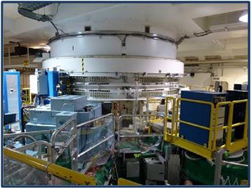
Figure 5 – Neutron Reactor in C-Hall
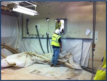
Figure 6 – View from C Hall to D Hall
The alignment team was able to complete the necessary data collection and the resulting network accuracy met the project requirements. This validates the use of the SA
simulation software as a good planning tool for complicated networks. Additionally, this network will need to be checked as the loading of the floors with glass beam segments, vacuum vessels and heavy steel shielding is added to each area. Typically, the control network will show movement greater than the accuracy requirements and will need to be measured at least a second time to quantify the settling and movement. This has not yet been performed on the NCNR beam expansion project, but is in the project schedule.
2.2 Characterizing Glass Beam Segments
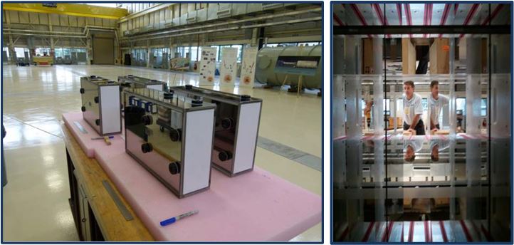
For the new beam lines, 145 new glass beam line segments were acquired from a supplier in Switzerland. These glass “boxes” are manufactured to be highly accurate, highly polished, nickel coated components that direct the neutron particles from the reactor along the beam line to the experiments in the guide halls. Figure 7 A shows four of the glass segments with measurement pucks epoxied to the sides and a protective cover on the ends to keep out dust and prevent damage. Figure 7 B provides a unique glimpse at the interior of the glass beam guides prior to joining. The pucks are used as auxiliary points to locate the glass segments once they are placed in their vacuum vessels. These points also are known by a more technical term, fiducials. The fiducials have values relative to the geometric center of the glass beam line segments. Once the beam segments are placed in their vacuum vessels, the fiducials are all that are visible and the centers are covered by adjoining beam segments.
Figure 7 A & B – Glass Beam Segments with Fiducials and Interior View
To value the fiducials, each beam segment is measured using a portable CMM (PCMM) arm at the 4 corners of each end and then the centerline is calculated. The fiducials are then measured and given values relative to the position of the beam segment centerline. The end planes are also measured to give the fiducials values along the beam line relative to the starting point of the beam line. Complicating the location even more is that each beam line is actually not a true line but a very large radius curve. The radii vary by beam line but are as large as 20,000 inches (2,500 ft) and the beam segments must be placed tangent to the curved beam path as they are aligned along the nominally designed path.
Figure 8 on the next page depicts a beam segment being measured using the PCMM arm. This process is repeated for all 145 beam segments and the values of the fiducials allow the placement of the beam segment in its proper location along the beam line.
Figure 8 – PCMM Arm Measuring Beam Segment and Fiducials
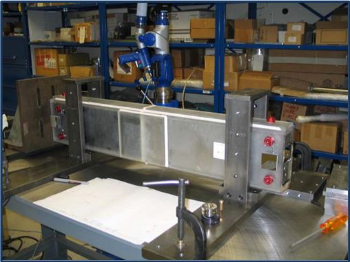
The key challenge in measuring the beam segments and valuing the fiducials is the placement of the fiducials where they will be most visible once they are installed in the vacuum vessel and ensuring the fiducials are valued based on where the glass segment is to be installed along each of the 4 new beam lines.
Figure 9 below provides a graphical representation of several beam segments in a vacuum vessel. The vessel “windows” had to be designed in the early stages of the project to coincide with the location of the fiducials so they would be visible during alignment. The alignment team worked closely with project engineers to ensure that the windows and fiducials were properly located to maximize visibility from proposed instrument locations.
Figure 9 – CAD Image of Vacuum Vessel with Beam Segments and Fiducials
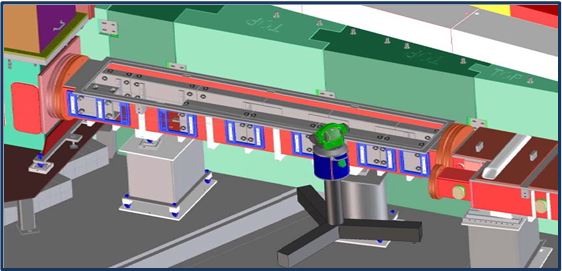
In the figure below, an actual picture of a vacuum vessel provides confirmation of the coordination of the fiducial placement and the windows installed in the vacuum vessel.
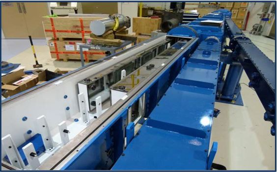
Figure 10 – Beam Segments Installed in Vacuum Vessel
2.3 Aligning C & D Hall Components in Temporary Location
The temporary alignment of D-Hall components was also necessary due to significant amount of demolition and concrete work required in the utility hall to prepare it for the new beam lines. The new guide hall (G Hall) was used to stage the vacuum assembly during temporary alignment. Control points, initially valued for the beam lines to be set in the new guide hall, were used as temporary control to locate the D Hall components prior to movement into the D Hall upon construction completion. Figure 12 is the CAD rendering of the D-Hall components aligned in the G Hall prior to movement.
Figure 12 – D Hall Vacuum Vessels Temporarily Assembled in Guide Hall
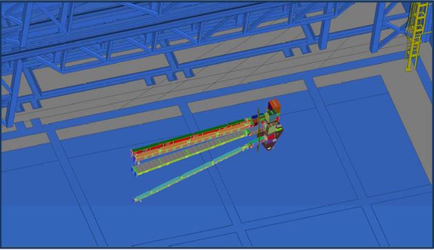
This temporary alignment is slated to save several weeks on the critical path of the beam line expansion schedule. The only significant risk remains the potential movement of beam segments within the vacuum vessels as they are moved into the D Hall. Steps have been taken to move the vacuum vessels on air bearings to minimize the potential for movement of any aligned components.
2.4 Positioning Vacuum Jacket Assemblies into Final Locations
Another major challenge for the NCNR alignment team was the installation of the beam line vacuum vessels containing the glass beam segments in their final positions. The process starts with the installation of the new reactor penetration, called an “inpile”. The inpile installation exposes the alignment team to potential radiation and must be completed as quickly and efficiently as possible. The installation is critical as it is the first component that sets the direction and orientation of the beam lines and must be set to coincide with the concrete wall penetrations established between the Reactor Hall and the Utility Hall. Figure 13 A & B show the inpile before installation and after installation in the reactor face.
Figures 13 (A) & (B) – Inpile Before and After Installation in Reactor Face
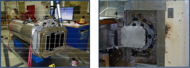
The image on the left shows the separation of the neutrons into 4 distinct segments prior to departing the reactor and entering the beam lines. The image on the right shows the inpile installed and several fiducials located around the collar to be used for alignment and valuing additional control points relative to the inpile.
Once the inpile is in place and the concrete wall penetrations have been completed (See Figure 6), the C-Hall components (See Figure 11) can be transferred into the Reactor Hall and accurately located. This process is facilitated by placing fiducials on the vacuum vessel jackets. These fiducials, shown below in Figure 14, were valued after the glass beam segments were installed allowing the indirect measurement of the beam segments without removing the covers on the vacuum vessels.
Figure 14 – Reactor Hall Vacuum Vessels with Fiducials
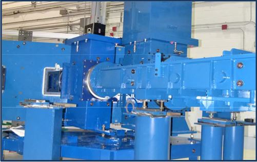
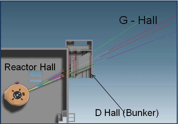
With the Reactor Hall vacuum vessels installed, the process can proceed to installing the D Hall vacuum vessels initially aligned in the main guide hall previously (See Figure 12). The challenge with this installation is that the final D Hall height is only 5 ft from floor to ceiling. The floor was raised to accommodate utilities that needed to be run under the vacuum vessels. This area, affectionately referred to as “the bunker” allowed for very little access room. The control network for D Hall also presented difficulties since visibility within the room is severely restricted. This necessitated placing some of the control points on the ceiling to maximize visibility. The final step is the installation of the vacuum vessels and glass beam guides in the guide hall. Figure 15 below gives a good overhead view of the 3 areas.
Figure 15 – Reactor Hall, D Hall, Guide Hall Spatial Relationship Reactor Hall D Hall (Bunker) G – Hall
With the completion of the installation of the Guide Hall vacuum vessels, the primary alignment tasks are complete and the only remaining task is the installation of the experiment equipment for each of the 4 beam lines.
2.5 Using Non-Metrology Personnel to Perform Alignment Tasks
A remarkable aspect of the beam line expansion project, other than the need for the highest level of accuracy, the need to work on the periphery of the project construction areas and dealing with severely limiting visibility constraints is the fact that all of the NIST personnel performing the alignment planning and measurements had no previous experience with metrology or alignment. This lack of experience, though initially intimidating, also meant that no bad habits had been ingrained. The operators were taught to run PCMM arms, laser trackers, total stations, digital levels as well as the NRK SA software platform. The training also included best practices in the use of metrology equipment and alignment techniques for accurately setting components using a control network.
The success of the alignment process thus required a significant amount of careful planning, hands on training using actual beam line components and guidance from an experienced metrology expert to ensure the effort stayed on target and avoided common pitfalls that would only be known to someone who had worked in the alignment arena for many years.
ECM Global Measurement Solutions (ECM) was privileged to be asked to assist with the NCNR beam line expansion project. The guidance came in the form of project site reviews, procedure development, automated measurement function development and onsite training of the alignment team. Of these efforts, the development of a specific alignment plan and procedures was one of the most critical elements.
ECM personnel wrote a project plan that was used as a template for the alignment team. Included in the project plan was a step-by-step approach to planning each measurement task and coordinating alignment requirements with the other disciplines on the project including the design engineers responsible for vacuum vessels. This coordination ensured that when the time came for positioning beam segments and vacuum vessels that visibility restrictions were taken into account and provisions made for optimizing line-of-sight to critical components.
Additionally, where the complexity or repetitiveness of a measurement task necessitated a guided approach, software routines were developed that would step the lab technicians through the measurement task and perform the computations automatically.
Figure 16 below provides an example where the NRK SA software was used to automate the measurement of each beam line segment, directing the operator of the PCMM arm which points to measure, in which order and then computing the alignment and transforming the fiducials into project coordinates. This level of scripting or automated measurement not only simplifies the measurement task but eliminates many manual data entry steps that could prove sources of measurement error.
Figure 16 – NRK SA Measurement Plan For Measurement Automation
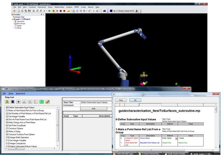
The use of the NRK SA software also provided a visual guide during each of the measurement tasks where the lab technicians could see the data as they collected it and verify that the points were taken per the measurement plans and procedures. It remains one of the most significant accomplishments of the NCNR beam line expansion project to see the development of the lab technicians into a first rate measurement and alignment team. The success of the project hinged on their capabilities and they delivered with both the discipline and determination to meet the project challenges.
3.0 Conclusions
The NCNR alignment team faced several daunting challenges during the installation of the new beam lines while the main facility was still operating. Working adjacent to areas where active neutron experiments were being conducted required careful planning and execution to avoid testing interruptions. The team also had to ensure the project met its accuracy, schedule and cost targets. That all this was accomplished by lab technicians and engineers with little or no formal metrology or alignment training is a remarkable feat and reflects well upon the quality of the engineers and technicians assigned to the alignment team.
The team’s ability to install and value the highest order accuracy control network, using multiple measurement technologies from PCMM arms to laser trackers and levels demonstrates a great aptitude for acquiring new skills and performing them at a very high level. The willingness to work on the most critical tasks while delegated to performing them in whatever available space was on-hand in adjacent areas to the main construction site is a credit to the team. The planning behind placing the fiducials in the most visible locations on the beam segments and vacuum vessels and incorporating the location into the CAD designs for optimizing the alignment process is a thoroughness not commonly found on complicated alignment projects. And to accomplish all this with a crew of technicians and engineers with no previous metrology experience is quite extraordinary.
Clearly, though the project presented significant alignment challenges, the NCNR team was up to the challenge and demonstrated the skills necessary to ensure a successful installation of the new beam lines.
